Introduction
Tutorials
Improving a discharge simulation
A Geometry configuration describes the lengths and angles of the different casing, liner or open-hole sections of a well, with their diameters and roughness.
This tutorial show you how to enter a geometry configuration for a vertical well:
To enter a geometry configuration for a deviated well instead, see here.
This uses the well MYWELL, that you should have created earlier.
You will enter data for this well:
| Section | From [m] | Down to [m] | Casing or liner |
|---|---|---|---|
| 1 | 0 | 900 | Casing 9 5/8" 47 lb/ft |
| 2 | 900 | 2500 | Slotted Liner 7 5/8" 29.7 lb/ft |
NOTE
Measure all depths relative to the same point at the wellhead read more.
This well is vertical, so measured depth equals vertical depth.
For each well section, you only need to enter the depth of the bottom of the section.
Open the sample database if it is not already open.
Click  to select this well for the tutorial.
If necessary, click the  in front of to display the WellSim data types.
Under , click Geometry configurations.
Right-click in a row under Description to pop up a menu:
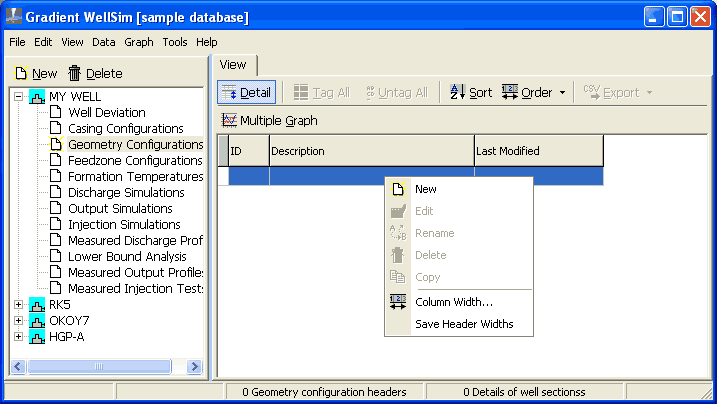
Click New in the menu. WellSim creates a new, empty geometry configuration. Click the  tab (top left). The window should look like:
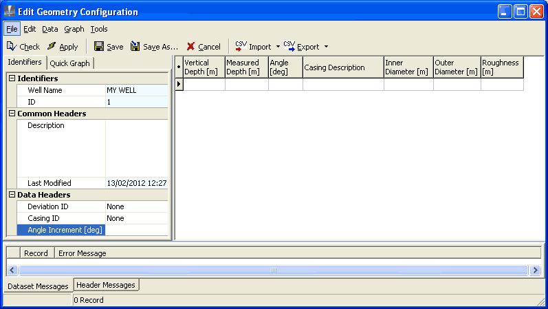
Before you enter data, read these tips for entering data.
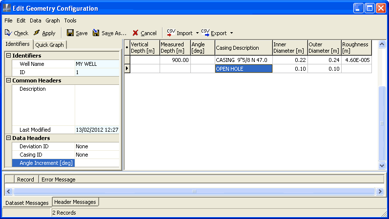
Enter this data into the empty row at the top, right of the window:
| Data | Enter | Note |
|---|---|---|
| Measured depth | 900 |
[m] The depth of the bottom of the first section (below ground level at the wellhead) |
| Casing description | Casing 9 5/8 N47.0 |
Choose from the drop-down list. Click in the Casing description field, then click  to display the drop-down list, scroll up or down the list, then click the Casing description to use. After you choose a casing, WellSim fills in the diameters and roughness. to display the drop-down list, scroll up or down the list, then click the Casing description to use. After you choose a casing, WellSim fills in the diameters and roughness. |
Press Down arrow on the keyboard. WellSim creates a new, empty row:
Enter this data in the new empty row:
| Data | Enter | Note |
|---|---|---|
| Measured depth | 2500 |
[m] The depth of the bottom of this section (below ground level at the wellhead) |
| Casing description | Liner 7 5/8" N29.7 |
Choose from the drop-down list |
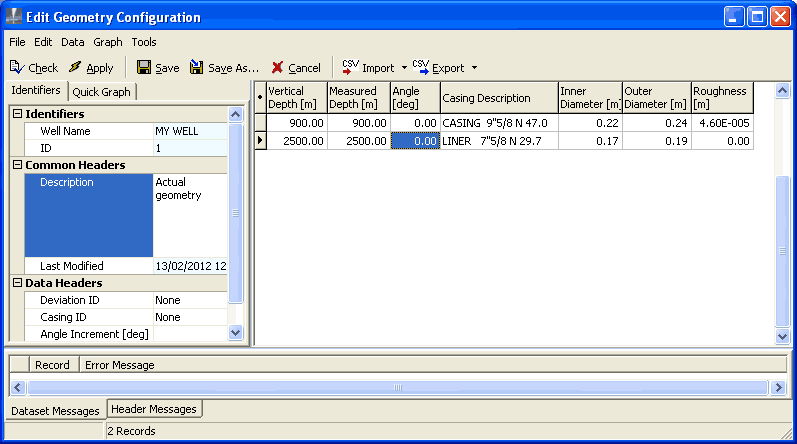
Your window should now look like:
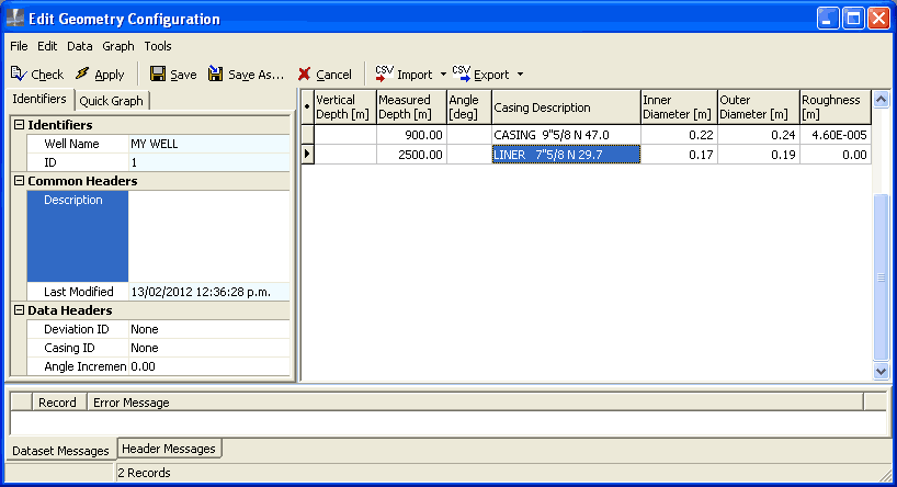
Note: The above data is incomplete, because you have not yet entered a description or specified that the well is vertical.
Click  .
.
WellSim displays a message that the data you have entered has errors. Click OK.
Now, find and fix the errors:
Click  at the bottom of the window. In the
 Header messages tab at the bottom of the screen, WellSim displays an information message (starts with an I) that you have not entered a description for the new geometry configuration.
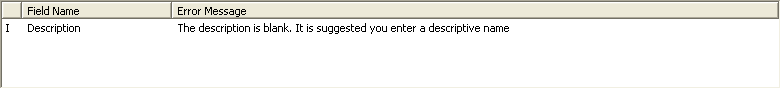
Click Description (in the tab, left side of window) and type Actual geometry.
Click  at the bottom of the window. In the
 Dataset messages tab at the bottom of the screen, WellSim displays error messages (start with E), that vertical depth and angle are both empty (one of these needs to be entered). WellSim also displays information messages (start with I) that it can calculate vertical depth from angle or angle from vertical depth.
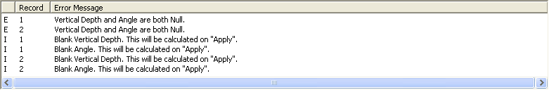
Click Angle in the first section and type 0.
Click Angle in the second section and type 0.
Click again. Now there should be no error messages.
WellSim will calculate any data it can that you have not entered.
 .
.In this case, WellSim calculates the vertical depths of the bottoms of the well sections, and the window should look like:
 .
.
 does:
does:
When you have entered or edited any dataset, normally just click , rather than clicking and first.
To ignore the data you have just entered and exit, click  .
.
Save As is the same as Save, except that WellSim creates a new geometry configuration for the well with the same data as this geometry configuration and a new description.
For example, you might have already created a geometry configuration with the actual well geometry and saved it. To create a new geometry configuration with different casing and liner sizes:
Edit the actual geometry configuration to change the casing and liner sizes.
Click  .
.
Type a new description for the new geometry configuration and click OK.
For some wells, a length of casing completely overlaps another. For example, a medium diameter casing from ground level down to 1000 m and a wider diameter casing from ground level down to 100 m. In this case, it is optional to enter the wider diameter casing. If you do enter it, WellSim will ignore it, because it does not affect the well's flow.
For some wells, a length of casing partially overlaps another. For example a casing down to 1000 m and an inner liner starting at 950 m and going down to 2500 m. In this case, enter the depths where the inner diameter changes; in this example enter 950 m for the bottom depth of the casing and 2500 m for the bottom depth of the liner.
WellSim assumes that liners are slotted along their entire lengths. If your liner is solid, enter it as a casing with the same size. If your liner has solid and slotted sections, enter it as several sections:
If you want to base your custom values on an existing casing or liner:
In the Casing description dropdown list, select the casing or liner to base your values on.
This sets Outer Diameter, Inner Diameter and Roughness in the line for that section. Note these values.
Set your custom values:
In the Casing description dropdown list, select Non-standard casing.
Enter the required Outer Diameter, Inner Diameter and Roughness.