Introduction
Tutorials
Improving a discharge simulation
This tutorial shows how to model the effect of a different well geometry on output. For more on using WellSim to model what-if scenarios like this see here.
This tutorial uses:
The BottomUp discharge simulation Better BU 100 t/hr
The BottomUp output simulation From better BU 100 t/hr that you should have entered earlier.
This tutorial follows the basic steps for a BottomUp what-if scenario described here.
In this tutorial you will:
In this tutorial you will make copies of existing simulations, change them as necesssary and run them. This avoids having to write down and reenter data.
The change required for this what-if scenario is to use a new geometry configuration with larger casing diameters.
Create a copy of the geometry configuration Actual geometry and open the copy for editing.
Change:
Bigger geometry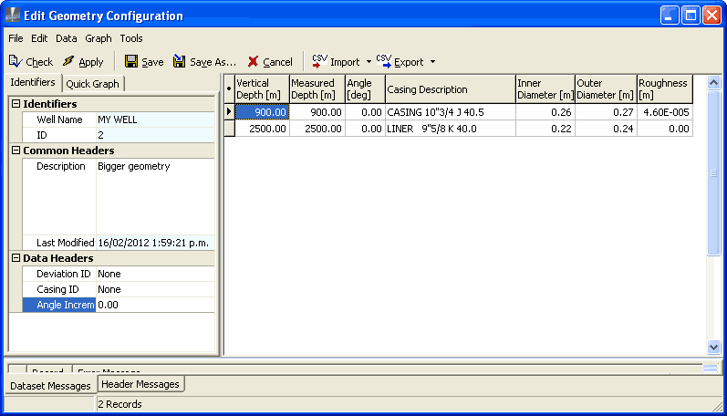
Apply and save this new geometry configuration.
Create a copy of the discharge simulation Better Bu 100 t/hr and open the copy for editing.
Change:
Bigger geometry BuBigger geometry:The other default values are correct, because we are not modelling other changes.
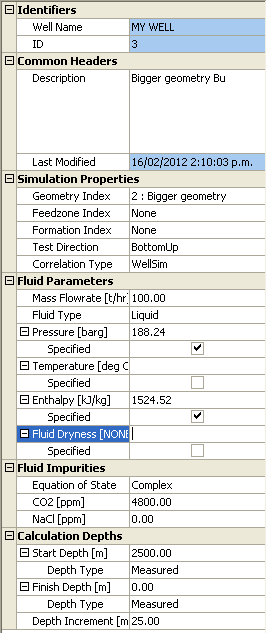
Run and save the discharge simulation.
Create a copy of the output simulation From better Bu 100 t/hr and open the copy for editing.
Change:
Bigger geometryBigger geometry BuCalc Drawdown so we can specify a linear drawdown factor; the default, 0.118 bar/t/hr is correct, so there is no need to enter itThe other default values (such as reservoir pressure) are correct, because we are not modelling other changes.
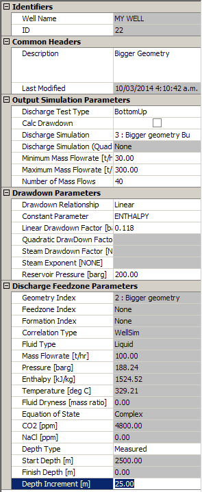
Run and save the output simulation.
In MY WELL's Output Simulations window, tag  :
:
Bigger geometry
a TopDown output simulation (uses actual geometry), such as From better TD 100 t/hr.
Click  to see the two output simulations:
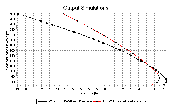
The red line is for the larger bore geometry.