Introduction
Tutorials
Getting familiar with GeoData Manager
Changing how GeoData Manager looks
Scenarios for using GeoData Manager
Data types and nodes
Help with data types and nodes
Getting familiar with GeoData Manager
Changing how GeoData Manager looks
Scenarios for using GeoData Manager
Help with data types and nodes
The Chemistry module is used to store the results of chemical analyses of geothermal fluid samples (water, steam and gas), as well as soil samples. The chemical composition of rocks is stored in the Geology module.
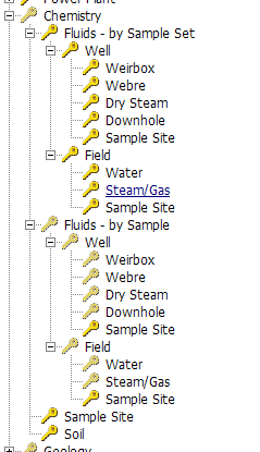
The sub-nodes of this module include:
GeoData Manager has the option to enter chemistry values as detection limits, for example <1 ppm.
Click Settings, then click General settings:
Set the field Chemistry:
 Detection limits option on (the default). Enter
 -28 or <28 for a measurement and GeoData Manager will display <28
 Detection limits option off. GeoData Manager displays measurements exactly as you enter them.
If you have the option on and enter some detection limits, then if you turn the option off, those detection limits, and any calculations using them, will be negative numbers.
GeoData Manager handles any values calculated from detection limits appropriately, for example:
Adding or subtracting
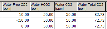
Detection limit values, eg <10 ppm, are treated as zero, for example:
Water Total Cations: the total equivalence (valency x concentration / molecular weight) of the major cations (Li, Na, K, Ca, Mg and H).
Water Total Anions: The total equivalence of the major anions (F, Cl, SO4, HCO3, CO3, OH).
Water Total CO2: the molar sum of HCO3, CO3 and Free CO2. This is only calculated if there is a value for each of the three components. A detection limit is treated as a value of zero.
For example:
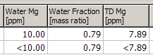
Multiplying
The detection limit is multiplied:
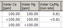
Dividing
Fluid chemistry data traditionally consists of the analyses of a (large) number of individual samples, associated with the sample site (well, spring, fumarole, etc), the type of sample and the date of collection. To assist in the organisation of this data, GDManager has introduced the concept of a Sample Set, to group samples with similar characteristics from each sample site. For instance, production samples from a well could be in one sample set, pre-production samples in a different sample set, while downhole samples would be in another. Production samples could be further divided into yearly intervals (e.g. PRODUCTION99) if appropriate.
At this node and sub-nodes, data sets containing multiple samples can be selected for graphing and reporting. This is often more convenient than selecting individual samples, but depends critically on how you have organised your sample sets.
Data editing functions (New, Edit, Rename, Delete) are available only at sub-nodes of this node.
Square brackets [ ] indicate the value in a field of the fluid chemistry database, chemdata. If you have used the Preferred Name option in the Unit System, the field may have a different name.
All formulae use log to base 10.
These nodes allow only data presentation functions.
Chemical constituents in both water and steam/gas samples are stored as weight ratios, in kg/kg (or kg/l) units, but can be entered and reported in mole-based units. The conversion factor is automatically calculated for each constituent. Calculated constituent ratios are stored as mole ratios, but can be presented as weight ratios. Dry gases are stored as mole percentages, not as weight percentages, and at present cannot be converted to weight percentages.
Fluid chemistry samples can be allocated to one of six sample types, obtained either from a geothermal well or from a field source, at the sub-nodes listed below:
Weirbox - water sample from atmospheric weirbox, steam/gas sample at any specified gas sampling pressure.
Webre - water sample at specified water collection pressure from a pressure separator, steam/gas sample at any specified gas sampling pressure.
Downhole - combined water/gas sample obtained using a downhole sampler.
Dry Steam - steam/gas sample obtained from a well discharging dry steam.
The allowable sample type codes, corresponding to the nodes above, are as follows:
At present, these codes cannot be changed, but may be able to be user-customisable in the future. If and when this occurs, the existing sample types of all samples will be automatically changed when user-specified codes are defined.
GDManager provides an extensive range of chemical calculations on each sample, with calculated results stored in the database to facilitate rapid access at a future time. The calculations are dependent on the sample type.
The most complete fluid chemistry sample is composed of both a water sample and a steam/gas sample. The samples can be collected under different sampling conditions, but provided the discharge conditions of the fluid source (e.g. a geothermal well) are the same, the two samples can be entered as a single sample in GDManager.
This combined-sample entry is available only for samples from two-phase discharging wells, with WELLWEIRBOX or WELLWEBRE sample types. Downhole samples can be considered to be a combined water/gas sample, and are treated slightly differently in the chemical calculations. Note that calculations on samples from a well discharging dry steam (sample type = WELLDRYSTEAM) are different than a steam/gas sample from a two-phase well (sample type = WELLWEIRBOX or WELLWEBRE). These differences are explained below.
Samples from sample sites other than geothermal wells (e.g. from hot or cold springs, fumaroles, rivers, etc) are known as field samples. No combined-sample calculations are carried out as the flash conditions are unknown. It is recommended that samples are entered either as a water sample (sample type = FIELDWATER) or a steam/gas sample (sample type = FIELDSTEAM).
The following fields are required for complete calculations.
[Water Collection Pressure] - WCP - for WellWeirbox and Field Water samples, this is set to local atmospheric pressure (0 Pa gauge). For other samples, the water collection pressure must be entered.
[Gas Sample Pressure] - GSP - required for gas calculations.
[Production Separator Pressure] - PSP - if greater than than Water Collection Pressure, double-flash is assumed, if less than Water Collection Pressure, value is ignored.
[Enthalpy defined by] - this field defines the enthalpy value to be used for flash calculations. If a reservoir temperature is defined, the liquid enthalpy (Hf) at that temperature is used. To copy the selected [Enthalpy defined by] value to all successive records while in Edit mode, use the Tools | Column Fill option. The following enthalpy options are available:
[Water CO2] - this is the total CO2 in the water sample, derived from HCO3 and CO3 ions, as well as dissolved CO2. In the pH range between 5 and 8.5, the dominant species will be the HCO3 ion. In this case, it is possible to enter HCO3 mass concentrations, provided they are first adjusted by the factor of 44/61.
Alternatively, a special ppm_HCO3 unit could be created in the Units System, with a factor = 61/44 = 1.386363636. This would allow HCO3 concentrations to be directly entered in ppm HCO3 and automatically converted to CO2 concentrations. Nore that this conversion is correct only for pH values between 5 and 8.5.
[Water Collection Temperature] - boiling temperature calculated from the water collection pressure for Weirbox and Webre samples (pure water assumed).
[Atmos Pressure] - calculated from the sample site elevation, Elev, as follows:
[Atmos Pressure] = 101325 + (-11.8834 x Elev) + (4.88456E-04 x Elev x Elev) (in Pa)
[Water Total Cations] - uses Li, Na, K, Ca, Mg and H concentrations, converted to meq/l.
[Water Total Anions] - uses F, Cl, CO4, OH and (CO3 + HCO3) concentrations, converted to meq/l. The (CO3 + HCO3) value in meq/l, is calculated from [Water CO2] (total CO2 in kg/l) and [Water pH], pH, as follows:
pH < 5 (no carbonic ions): (CO3 + HCO3) = 0
5 <= pH < 8.5 (only HCO3 ions present): (CO3 + HCO3) = [Water CO2]/61 x 1E6
8.5 <= pH <= 12 (HCO3 and CO3 ions present): (CO3 + HCO3) = (Y x [Water CO2]/6100 + (100-Y) x [Water CO2]/3000) x 1E6
where Y = 0.519125 pH^4 - 17.4216 pH^3 + 204.958 pH^2 - 985.793 x pH + 1657.68
pH > 12 (only CO3 ions present): (CO3 + HCO3) = [Water CO2]/30 x 1E6
[Water Ion Balance %] - calculated from the total ions expressed in equivalents, as follows:
The cation geothermometer calculations listed here use standard weight concentrations (kg/kg or kg/l), except for [T NaKCa] which uses mole/l, and [T K-Mg G], [T SiO2 FP] and [T SiO2 Cond] which use ppm. T K-Mg G is dependent on the water fraction (WF) at the water collection pressure and is not calculated until after flash and enthalpy calculations. If silica is not used to calculate reservoir enthalpy, the silica geothermometers are calculated using the formulas below. Otherwise an iterative procedure is used.
Enthalpies are calculated if the corresponding temperature falls between 125 and 369 deg C, otherware a null value is returned.
[T NaKCa] and [Beta] - standard Na-K-Ca geothermometer, given by:
[T NaKCa] = (1647/(log([Water Na]/[Water K]) + [Beta] x log(sqrt([Water Ca])/[Water Na]) + 2.24)) - 273.15
[Beta] = 4/3 if sqrt([Water Ca])/[Water Na] > 1 and [T NaKCa] < 100, otherwise [Beta] = 1/3.
[T NaK F] - Fournier Na-K geothermometer, given by:
[T NaK F] = (1217.0 / (log ([Water Na]/[Water K]) + 1.483)) - 273.15
[T NaK T] - Truesdell Na-K geothermometer, given by:
[T NaK T] = (855.6 / (log ([Water Na]/[Water K]) + 0.8573)) - 273.15
[T K-Na G] - Giggenbach K-Na geothermometer, given by:
[T K-Na G] = 1390.0 / (1.75 - log ([Water K]/[Water Na])) - 273.2
[T K-Mg G] - Giggenbach K-Mg geothermometer, given by:
[T K-Mg G] = 4410.0 / (13.95 - log([Water K] x [Water K] x [Water Fraction]/[Water Mg])) - 273.16
[T SiO2 FP] - silica geothermometer assuming adiabatic cooling, given by:
[T SiO2 FP] = -42.1981 + 0.288313 x SiO2 - 3.66863e-4 x SiO2 x SiO2 + 3.16647e-7 x SiO2 x SiO2 x SiO2 + 77.03438 x log(SiO2)
where SiO2 = reservoir silica concentration = [Water SiO2] x [Water Fraction]
[T SiO2 Cond] - silica geothermometer assuming conductive cooling, given by:
TSiO2Cond = -42.1981 + 0.288313 x SiO2 - 3.66863e-4 x SiO2 x SiO2 + 3.16647e-7 x SiO2 x SiO2 x SiO2 + 77.03438 x log(SiO2)
where SiO2 = measured silica concentration = [Water SiO2]
[H NaKCa] = water enthalpy (Hf) at [T NaKCa] temperature.
[H NaK F] = water enthalpy (Hf) at [T NaK F] temperature.
[H NaK T] = water enthalpy (Hf) at [T NaK T] temperature.
[H SiO2] = water enthalpy (Hf) at [T SiO2 FP] temperature.
If silica is used to calculate reservoir enthalpy, iterative calculations are used to calculate the silica geothermometers and enthalpies. Otherwise, the formulas in the preceding sections are used.
SiO2 x Hg/(Hg - Hf) = -3.55320 + SiO2 x H/(Hg - Hf) + 0.146005 x H - 4.92698e-4 x H x H + 1.23047e-6 H x H X H - 4.94207e-10 x H x H x H x H
where Hf and Hg are liquid and vapour enthalpies at water collection pressure.
If the well has excess enthalpy, the reservoir silica concentration, SiO2, is adjusted until:
SiO2 = [Water SiO2] x (Hg - Hr)/(Hg - Hf)
where Hr = reservoir enthalpy corresponding to TSiO2FP
and Hf and Hg are liquid and vapour enthalpies at water collection pressure.
[T SiO2 FP] - Fournier and Potter silica geothermometer assuming adiabatic cooling, given by the temperature at which water enthalpy (Hf) is equal to [H SiO2].
[T SiO2 Cond] - Fournier and Potter silica geothermometer assuming conductive cooling. Not adjusted for excess enthalpy.
[Water Fraction] - calculated from the water collection pressure and specified reservoir enthalpy, with the following special cases:
[Steam Fraction] - calculated from the gas sample pressure and specified reservoir enthalpy, with the following special cases:
[Reservoir Temperature] - calculated and filled according to the [Enthalpy defined by] field, as follows:
[H Excess] - the excess enthalpy of a discharging well, calculated as the difference between the measured discharge enthalpy and the reservoir enthalpy as specified by the [Enthalpy defined by] field. If reservoir enthalpy is calculated from silica, the reservoir silica concentration, SiO2, is adjusted until:
SiO2 = [Water SiO2] x (Hg - Hr)/(Hg - Hf)
where Hr = reservoir enthalpy corresponding to [T SiO2 FP]
and Hf and Hg are liquid and vapour enthalpies at water collection pressure.
[Excess Steam %] - percentage of excess steam, given by:
[Excess Steam %]= 100 x ([Enthalpy] - [H SiO2])/Hfg
where Hfg = HgSiO2 - [H SiO2].
GDManager calculates reservoir concentrations for 12 major constituents that do not partition into the vapour phase. Partitioning components (CO2, H2S, NH3, O-18 and Deuterium) are described elsewhere. For all constituents listed below, the reservoir concentration = water sample concentration x water fraction (calculated from reservoir enthalpy).
For historical reasons, the prefix TD (Total Discharge) is used, as total discharge concentrations equal reservoir concentrations for wells without excess enthalpy. To avoid confusion, the names of the TD fields can be changed by using the Preferred Name option in the Unit System.
Ratios of a number of major constituents are calculated. These are stored as mole ratios, but can be displayed as weight ratios by using the unit conversion function in GDManager. The conversion factor is automatically calculated for each of these ratios:
Gas concentrations can be entered in three different formats, as follows:
all gases as concentrations in steam.
major gases (CO2, H2S and NH3) as concentrations in steam, minor gases as dry gas percentages.
all gases as dry gas percentages.
This option is detected by the presence of data in any of the following fields:
The concentrations of CO2 and H2s are calculated as weight per cent in the steam. Note that the formulae used inlcude the mass of the gas, and so are more accurate for high gas concentrations.
[CO2 Wt %] - the percentage of CO2 gas in steam by weight, given by:
[CO2 Wt %] = 100 x [Gas CO2] / (1 + [Gas CO2])
[H2S Wt %] - the percentage of H2S gas in the steam by weight, given by:
[H2S Wt %] = 100 x [Gas H2S] / (1 + [Gas H2S])
The reservoir (TD) concentrations of CO2, H2S and NH3, which partition into the liquid and vapour phase, are obtained from both the water and steam/gas cconcentrations, together with the water and steam fractions calculated from the specified reservoir enthalpy.
[TD CO2] - the reservoir concentration of CO2, given by:
[TD CO2] =[Water CO2] x [Water Fraction] + [Gas CO2] x [Steam Fraction]
[TD H2S] - the reservoir concentration of H2S, given by:
[TD H2S] =[Water H2S] x [Water Fraction] + [Gas H2S] x [Steam Fraction]
[TD NH3] - the reservoir concentration of NH3, given by:
[TD NH3] =[Water NH3] x [Water Fraction] + [Gas NH3] x [Steam Fraction]
If any of the four required quantities are absent, the reservoir (TD) concentration will not be calculated, except for the following cases:
[Molar Gas/Steam Ratio] - reservoir concentration of gases, calculated from the sum of all the gas concentrations converted to moles, as follows:
[Molar Gas/Steam Ratio] = ([Gas CO2]/mCO2 + [Gas H2S]/mH2S + [Gas NH3]/mNH3 + [Gas CH4]/mCH4 + [Gas N2]/mN2 + [Gas H2]/mH2 + [Gas O2]/mO2 + [Gas He]/mHe + [Gas Ar]/mAr) x [Steam Fraction] x mH2O
where mCO2 = molecular mass of CO2, mH2S = molecular mass of H2S, etc.
Nine gas constituents are expressed as mole fractions of the whole gas sample, excluding the water component of the sample. These are known as Dry Gas values. At present, it is not possible to calculate these values as mass fractions by mass. Dry Gas calculations are listed below, where mCO2 = molecular mass of CO2, mH2S = molecular mass of H2S, etc:
[Dry Gas CO2] - mole fraction of CO2 in total dry gas sample, calculated by:
[Dry Gas CO2] = [Gas CO2] / mCO2 x [Steam Fraction] x mH2O / [Molar Gas/Steam Ratio]
[Dry Gas H2S] - mole fraction of H2S in total dry gas sample, calculated by:
[Dry Gas H2S] = [Gas H2S] / mH2S x [Steam Fraction] x mH2O / [Molar Gas/Steam Ratio]
[Dry Gas NH3] - mole fraction of NH3 in total dry gas sample, calculated by:
[Dry Gas NH3] = [Gas NH3] / mNH3 x [Steam Fraction] x mH2O / [Molar Gas/Steam Ratio]
[Dry Gas CH4] - mole fraction of CH4 in total dry gas sample, calculated by:
[Dry Gas CH4] = [Gas CH4] / mCH4 x [Steam Fraction] x mH2O / [Molar Gas/Steam Ratio]
[Dry Gas N2] - mole fraction of N2 in total dry gas sample, calculated by:
[Dry Gas N2] = [Gas N2] / mN2 x [Steam Fraction] x mH2O / [Molar Gas/Steam Ratio]
[Dry Gas H2] - mole fraction of H2 in total dry gas sample, calculated by:
[Dry Gas H2] = [Gas H2] / mH2 x [Steam Fraction] x mH2O / [Molar Gas/Steam Ratio]
[Dry Gas O2] - mole fraction of O2 in total dry gas sample, calculated by:
[Dry Gas O2] = [Gas O2] / mO2 x [Steam Fraction] x mH2O / [Molar Gas/Steam Ratio]
[Dry Gas He] - mole fraction of He in total dry gas sample, calculated by:
[Dry Gas He] = [Gas He] / mHe x [Steam Fraction] x mH2O / [Molar Gas/Steam Ratio]
[Dry Gas Ar] - mole fraction of Ar in total dry gas sample, calculated by:
[Dry Gas Ar] = [Gas Ar] / mAr x [Steam Fraction] x mH2O / [Molar Gas/Steam Ratio]