Introduction
Tutorials
Getting familiar with GeoData Manager
Changing how GeoData Manager looks
Scenarios for using GeoData Manager
Data types and nodes
Help with data types and nodes
Getting familiar with GeoData Manager
Changing how GeoData Manager looks
Scenarios for using GeoData Manager
Help with data types and nodes
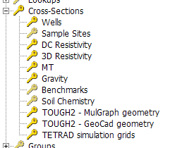
Cross-sections are also known as X-Sections:
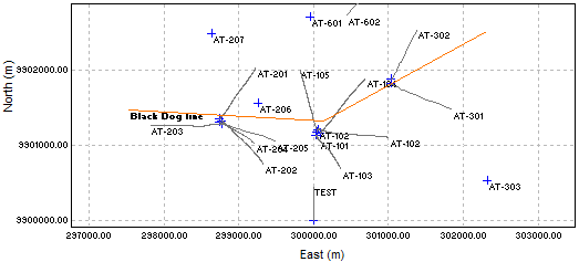
A cross-section is one or more connected straight-line segments on a map tab plus a list of sites which are assigned to that cross section. For example, here is a map showing cross section P1 in the sample database:
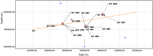
I set the map visibilities to show cross section P1 and GeoData Manager highlit and marked with an orange circle wells assigned to P1. A cross section is a line on a map, but it represents a vertical slice through the ground.
Cross sections are used by the  command in the toolbar, to project data onto a cross section in two dimensions and output it as a file read more. This file can then can be displayed by an external contouring application (such as Surfer)
This is a typical cross section displayed in Surfer, showing stratigraphy of wells along profile P1 in the sample database:
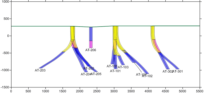
Note that the wells here are the wells highlit and circled in orange on the map above. As expected.
Cross section data sets are unusual in that each has two sets of detail data:
The coordinates (Locations E & N) of the ends of the straight-line segments. Work with these at the node Cross-Sections in the database tree.
The sites assigned to the cross section. Work with these at the appropriate sub-node of Cross-Sections.
For example, for a cross section where the sites are wells:
Enter or change the coordinates of the ends of the straight-line segments at the node Cross-Sections.
Enter or change the wells assigned to the cross section at the node Cross-Sections: Wells.
We expect cross sections to go from North to South or West to East, so enter the straight-line segments in these general directions.
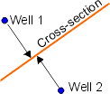
Data from a site appears on a cross section at the point where the cross section is closest to the site. This means that data from wells that are far apart can become close together on the cross-section:
Start the cross section well before the first site and end it well after. If the site is a well, start it well before the traces and end it well after.
If the cross section has more than one segment, files produced by have data arranged along the cross section as if it were straightened out:
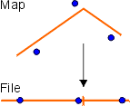
Sites appear to be further apart than they are. To reduce this effect, have each segment run in the same genaral direction and use one segment if possible.
Note:
Segments are numbered 1, 2 ..., in the order that you enter them.
The ends of a segment are called nodes. Segment 1 goes from node 0 to node 1, segment 2 goes from node 1 to node 2 ...
This tutorial shows how to enter a two-segment cross section. But the one-segment cross section, P1, is a better cross section for these wells than this.
There are two steps:
Enter the cross section's straight-line segments; you can do this with the mouse on a map, step 1a or by entering coordinates by hand, step 1b. You can enter the segments using the mouse, then change the coordinates by hand.
Assign sites to the cross section.
Go to a node with sites you will assign to the cross-section, eg for wells, go to Well and Drilling. Click Map View to see the sites.
You can enter a cross section on any map, but it is best to see the sites you will assign to the cross-section so you can place the segments in relation to these. You might want to tag the sites for the cross section and set the map tab visibilities to see only these sites.
Adjust the Map View area to include all sites, plus any well traces you wish to include on the cross-section. The Map View can not scroll while you enter the segments.
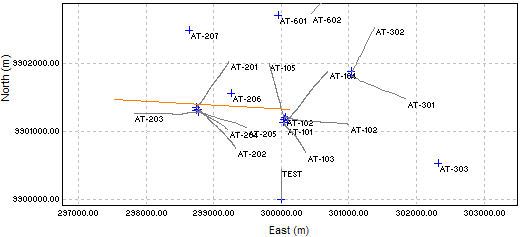
Click Add X-Section. Click the start of the first segment. Click the start of the second segment. The first segment turns orange:
Click the end of the second segment:
Click End X-Section:
Type a name for the cross section. You can change the coordinates if you want. Click OK:
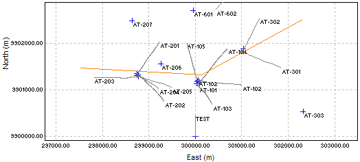
This map shows the new cross section:
Go to the Cross-Sections node in database tree.
Right-click in the header window and click New in the drop-down list.
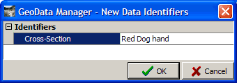
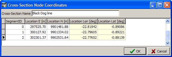
Enter the name of the cross-section in the Data Identifier window, and press OK.
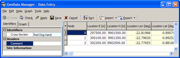
In the Data Entry window, enter rows for nodes nodes 0, 1 and 2 and enter the coordinates of each node. I used the coordinates from the cross section I entered with the mouse, rounded a bit.
To assign sites to a cross-section:
Navigate to the appropriate sub-node of Cross-Sections, for example to Cross-Sections: Wells to assign wells.
Right-click the cross-section and click Edit.
If no sites have been assigned to the cross-section yet, it displays:
This time, click Cancel to skip this.
It displays the window for assigning sites to the cross section, and there are two ways to do this. The first is to enter the wells, selecting from the drop-down list:
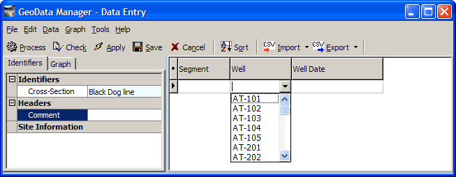
You need to note the well dates to enter, so this can be cumbersome.
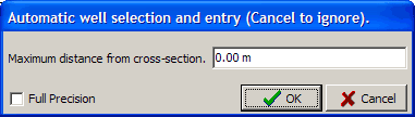
The second way is to click  :
:
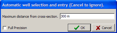
Enter a value here and GeoData Manager will automatically assign wells within this distance of the cross section to the cross section. Find a value by looking at a map or proceed by trial and error. 300 m gets a reasonable number of wells.
Now assign each site to the closest segment. By default all wells are assigned to segment 1.
The above map shows that wells AT-102, AT-104, AT-301 and AT-302 should be on segment 2, because their traces lie along this segment. Note that AT-102 is a redrill, and one of them might be better on segment 1; I put both on segment 2 so that their wellheads would be at the same place on the profile. Change the segments for these wells to 2:
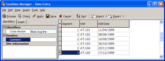
Click Save.