Introduction
Tutorials
Getting familiar with GeoData Manager
Changing how GeoData Manager looks
Scenarios for using GeoData Manager
Data types and nodes
Help with data types and nodes
Getting familiar with GeoData Manager
Changing how GeoData Manager looks
Scenarios for using GeoData Manager
Help with data types and nodes
These data types hold data for drilled or planned wells.
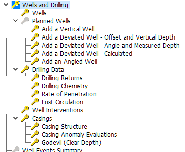
The Well and Drilling node has five categories:
The Wells node has data for the locations of drilled wells. There are four types of wells:
This section describes:
Data that GeoData Manager stores for each well
When a well is referenced in other types of data sets then it is said to have dependent data. For example if you have entered downhole PT measurements for well AA-321 then the PT measurements are dependent data for well AA-321.
Renaming a well (changing the well name or date) The name is also changed in all dependent data. You can not set the well date later than the date of any dependent data belonging to the well.
Deleting a well You must first delete any dependent data belonging to the well.
All wells are automatically assigned as sample sites for fluid chemistry samples. The implications of this are further discussed in the Fluid Chemistry module.
The tables are:
Wells can be assigned a user-defined Well Status, to facilitate data filtering and selection. Well Status is a lookup field which can be edited at Lookups > Well Module > Well Status.
Any well can be assigned a Well Suffix. This field is primarily used for reservoir simulation, where it may be necessary to allocate production data to a uniquely-named well, if the feedzones of a redrilled well are significantly different than those of the original well. Alternatively, the Well Date could be used.
The deviation of a well at any point is defined by the values of theese fields:
Measured Depth - the distance of the point from the wellhead measured within the well(positive downwards).
Vertical Depth - the vertical distance of the point from the wellhead (positive downwards).
Delta E - the horizontal distance of the point east of the wellhead.
Delta N - the horizontal distance of the point north of the wellhead.
If values are entered for all four fields, GeoData Manager checks to see if they describe a physically possible well. If either Measured Depth or Vertical Depth is not entered, GeoData Manager calculates the value from the other three values and assuming straight-line connection from the previous point in the well.
GeoData Manager also calculates four other quantities, using forward increments, as listed below:
The bottom hole point is assumed to have the same slopes as the previous point. For a vertical well, Slope = 1, ESlope = NSlope = 0.
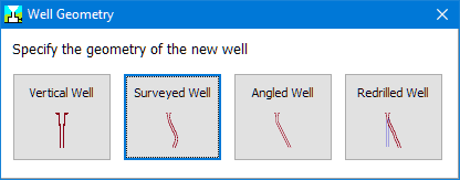
When you go to enter a new well, GeoData Manager asks what type of well it is:
Then, enter these identifiers:
| Field | Note |
|---|---|
| Well | Enter a unique name for the well. |
| Well Date | This must be earlier than the date of any data likely to be collected from the well. To include data collected during drilling, the well spud date is recommended. |
| Two values for location | Eithe E and N or Lon and Lat, depending on the Primary Location System. |
| Elevation | Enter the elevation of the casing head flange or the elevation of the drilling pad. Do not use the kelly bushing or similar - this can be handled with the RKB Height. |
| Max Measured Depth | Note that this is the measured depth down the well, not the vertical depth. |
| RKB height | The height above the value of elevation |
| Well category | The well's hole size - choose from the dropdown list |
| Well type | Choose from the dropdown list |
| Well status | Choose from the dropdown list |
Then enter geometry data for the well as described below. To change a well's type, change the field Well geometry.
A vertical well is fully defined by the location of the top and the depth.
If you enter Cased Depth or Major Feed Depth then they are automatically entered in the deviation table, marked as interpolated by a "Y" in the Interpolated column.
Deviation Corner Depth and WellAzimuth should be left blank; if you enter them they will be ignored. All deviation data in the Detail Table tab is automatically calculated, and any values you enter in the Detail Table tab will be overwritten.
A surveyed well is one where the well deviation is entered at a number of points down the well. At each point, the deviation is entered as distances east and north (Delta E and Delta N), relative to the wellhead location. If a well deviates towards the south or west, the entered deviations are negative. Deviation data can be entered in the detail tab in one of three formats:
Measured Depth, Vertical Depth, Delta E and Delta N; note that (Measured Depth increment)^2 must be greater than or equal to (Vertical Depth increment)^2 + (Delta E increment)^2 + (Delta N increment)^2.
Measured Depth, Delta E and Delta N.
Vertical Depth, Delta E and Delta N; in this case, Measured Depth is calculated in the Check procedure.
Enter as much header data as possible, including Cased Depth and Major Feed Depth. If you wish, you can fill Deviation Corner Depth, Final Drift Angle and WellAzimuth with values that approximate the well deviation, but these values are for information only, and will not be used in any checks or calculations.
An angled well is one where the well deviation is defined by the angle of the well from the vertical (Final Drift Angle) and its direction in degrees East of North (WellAzimuth). Note:
An angled well can also have an upper vertical section, with its length defined by Deviation Corner Depth.
An angled well with a non-zero Deviation Corner Depth can be used to approximate a well defined by kick-off point (KOP), rate of build (ROB) and final drift angle (FDA), before a well is surveyed. As an example, suppose a well has ROB = 10 degrees/100 m and FDA = 30 degrees. In this case, the curved part of the well is 300 m in length, and the Deviation Corner Depth is approximately half-way down, or 150 m below the KOP.
All deviation data in the Detail Table tab is automatically calculated, and any values you enter in the Detail Table tab will be overwritten.
Enter a well as a redrill if and when the location of an existing well in GeoData Manager changes, for example:
If a well becomes useless from deposition, it is closed off and a new well is drilled beside it.
If an existing wellhead elevation changes (eg, from subsidence, mining or landslip).
If you have not entered a redrill for a well then there is one well data set with that well name. Entering a well as a redrill means that it has the same name as the earlier well, but you will enter a later well date. There are now two (or more, you can enter more than one redrill) well records with the same well name and different well dates.
Note:
You do not have to enter a changed well as a redrill, but do so if you want to refer to the well by the same name. You could enter the changed well as a new well, in which case you must give it a new name (perhaps add a one-letter suffix to the original name).
When you enter a measurements for a redrilled well, for example a downhole PT run, GeoData Manager only requires you to enter a well name. When it needs information about the well, it looks in the well header table for wells of that well name and uses the test date to find the correct well.
Once you have entered a redrill for a well, you can not add measurements from before the redrill. If you want to do so, enter the next well as a new well, not a redrill. For example, if a well becomes useless from deposition and a new well is drilled beside it but the earlier well is not closed off and you continue to make pressure measurements down the earlier well then enter the next well as a new well, not a redrill.
For a redrilled well, you can enter a unique well inentifier to distinguish bewteen the configurations for 3D modelling see here.
The required fields are pre-filled with the values from the earlier well, as many of these will not change.
Enter a well date that is different later than the date of earlier well.
Right-click the well configuration to change and click Rename.
At the Data Identifiers window, type in the new Well Date. Note that you cannot change the well name here.
If the new Well Date means that the earliest well date is now later than the date of data belonging to this well, an error message is displayed and you will not be able to proceed.
If no data exists earlier than the earliest well date, the Well Date for this configuration is changed. This operation does NOT change the date of data measured in the well.
Right-click the well to delete and click Delete.
This does not delete any data measured in the well. If deleting this well means that the earliest well date is now later than the date of data belonging to this well, an error message is displayed and you will not be able to proceed.
Having redrilled wells means that there is more than one well with the same well name. But 3D modelling apps require every well to have a unique well indentifier. GeoData Manager lets you enter such an identifier in a well's header data. You can enter the identifier:
Either manually when you enter the other data for the well.
Or automatically:
Click Tools | Fill unique well identifier. For wells with no redrill, GeoData Manager inserts the well name as the unique identifier. For redrill wells, GeoData Manager does not insert a unique well identifier. GeoData Manager displays a message:
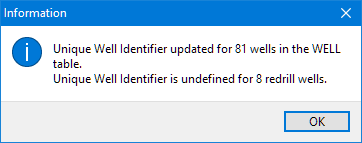
Go to each redrill well and manually enter a unique well identifier.
This node has data for the locations of planned wells. The data types are:
| Data type | Well Geometry field |
|---|---|
| Add a Vertical Well | Vertical |
| Add a Deviated Well - Offset and Vertical depth | Deviated_Offset |
| Add a Deviated Well - Angle and Measured Depth | Deviated_Angle |
| Add a Deviated Well - Calculated | Deviated_Calc |
| Add an Angled Well | Angled |
The data for a planned well is similar to the data for a well in Location and Deviation. There are three types of deviated well, depending on how you specify the deviation.
At the node Planned wells you can work with data for all types of planned wells, but you can not add new wells.
This node has data for drilling wells. The data types are:
The node Drilling shows the data for all types of drilled wells, but you can not add new wells.
This node has data for well interventions (miscellaneous events), for example for a clean, a workover or a redrill.
This node has data for casings of drilled wells. The data types are:
The node Casings shows the casing structure data sets, but you can not add new casing structures.
The casing of every well is determined by the well name and a date (the Casing Date). This allows a well to have one or many casing configurations. If the well is a multi-configuration well, the well configuration in use at the Casing Date is used to check that the casing is not deeper than the well. This check is carried out during New, Edit and Rename operations.
Well casing details have these lookup fields:
Casing Type is a hard lookup, which means that only the casing types shown in the dropdown list can be entered. User-defined casing types can be entered in the Lookups > Well module of GDManager, which means there is no practical restriction on casing types.
Note, however, that when a new casing type is entered in the Lookups module, a generic casing type must be assigned, by selecting a value listed in the ReferenceCode fields. Available types, used by GDManager to control graphical representation of well casings, are:
Casing Size is a hard lookup, which means that only the casing sizes shown in the dropdown list can be entered. An extensive list of pre-defined casing and liner sizes is provided in GDManager. Additional sizes can be entered by the user in the Lookups > Well module of GDManager. Open hole dimensions can also be entered - in this case, the ID and the OD should have the same value. Casing sizes that are not used can be deleted from the Casing Size lookup table, to shorten the dropdown list of sizes.
When a casing size is selected, the casing inner diameter (ID) and outer diameter (OD) are automatically entered in the casing detail grid. These sizes can be edited by the user, but this is not recommended unless the casing dimensions are different from normal because of effects such as scaling or casing damage. If a new casing size is employed, the details of this casing should be entered in the lookup table before casing data is entered into GDManager.
Connections and Slots are both soft lookups, which means that the user can type any information into these fields. However, it is recommended that a standard list of connections and slots are set up in the Lookups > Well module and these are used. This facilitates data entry and minimises errors.
At this node, information about casing anomalies can be entered. The fields listed below are all soft lookups. While any information can be entered in these fields, it is recommended that standard lists of values are set up in the Lookups > Well and in the Lookups > Reservoir modules. This facilitates data entry and minimises errors.
??